

How To Find Resistance Using Multimeter
How to Mensurate Resistance with a Multimeter
Knowing how to measure resistance with multimeter is easy - here we proovide some guidleines about how to make resistance measurements with a multimeter & provide some hints & tips.
Multimeter Tutorial Includes:
Test meter nuts Analogue multimeter How does an counterpart multimeter work DMM digital multimeter How a DMM works DMM accuracy & resolution How to buy best digital multimeter How to apply a multimeter Voltage measurement Electric current measurements Resistance measurements Diode & transistor test Fault finding transistor circuits
One important measurement that tin can exist made with a multimeter is a resistance measurement. Non only can these be made to check the accuracy of a resistor, or bank check it is functioning correctly, merely resistance measurements can be required in many other scenarios besides.
Information technology may exist to measure the resistance of an unknown conductor, or it may be to bank check for short circuits and open circuits.
In fact at that place are many instances where measuring resistance is of smashing interest and importance. In all these cases a multimeter is an ideal piece of examination equipment for measuring resistance
Resistance measurement basics
When measuring resistance, all musltimeters utilise exactly the same principle whether they are analogue multimeters or digital multimeters. In fact other forms of examination equipment that measure resistance likewise use the same basic principle.
The basic thought is that the multimeter places a voltage at the 2 probes and this will crusade a current to period in the detail for which the resistance is being measured. By measuring the resistance it is possible to determine the resistance betwixt the two probes of the multimeter, or other detail of exam equipment.
How to measure resistance with an analogue multimeter
Analogue multimeters are good at measuring resistance, although they are a few points to annotation near the manner in which it is done.
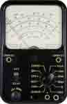
The start indicate to note is that as the meter itself responds to current flowing through the component under test. A high resistance corresponds to a low current and the meter needle settles on on the left manus side of the dial, and a low resisatnce corresponds to a college current and the meter needle deflects more than and then it appears on the right paw side of the dial equally shown beneath.
It volition also be noticed that the calibrations become much closer together equally the resistance becomes higher, i.e. on the left hand side of the dial.

Some other attribute of using an analogue multimeter for measuring resistance is that the meter needs to exist "zero'ed" before making a measurement. This is done by connecting the two probes together so that there is a short excursion, and then using the "zero" control to give full scale deflection on the meter, i.e. zero ohms.
Each time the range is changed, the meter needs to be nix'ed as the position may change from ane range to the next. The meter needs to be nada'ed because the full scale deflection volition alter according to aspects such as the land of the battery.
In that location are a few simple steps required to make a resistance measurement with an analogue multimeter:
- Select the item to exist measured: This may be annihilation where the resistance needs to be measured and estimate what the resistance may exist.
- Insert the probes into the required sockets Often a multimeter will have several sockets for the test probes. Insert these or bank check they are already in the correct sockets. Typically these might be labelled COM for common and the other where the ohms sign is visible. This is usually combined with the voltage measurement socket.
- Select the required range The counterpart multimeter needs on and the required range selected. The range selected should be such that the best reading tin can be obtained. Normally the multimeter role switch will be labelled with the maximum resistance reading. Choose the i where the estimated value of resistance will be nether but shut to the maximum of the range. In this style the virtually accurate resistance measurement can be made.
- Zero the meter: The meter needs to exist zero'ed. This is done past firmly placing the two probes together to give a short circuit and and then adjusting the zilch control to give a nothing ohms (total scale deflection) reading. This process needs to be repeated if the range is changed.
- Brand the measurement With the multimeter ready to make the measurement the probes can be practical to the detail that needs to be measured. The range can exist adjusted if necessary.
- Turn off the multimeter Once the resistance measurement has been fabricated, information technology is wise to turn the function switch to a loftier voltage range. In this way if the multimeter is used to again for another type of reading then no damage will be caused if it is inadvertently used without selecting the correct range and function.
Counterpart multimeters are ideal pieces of test equipment for measuring resistance. They are relatively cheap and they offer a reasonably good level of accurateness and general operation. They normally provide a level of accurateness that is more than sufficient for most jobs.
How to measure resistance with an digital multimeter, DMM
Measuring resistance with a digital multimeter is easier and faster than making a resistance measurement with an counterpart multimeter as there is no need to zero the meter. Every bit the digital multimeter gives a direct reading of the resistance measurement, there is too no equivalent of the reverse reading found on the analogue multimeters.
There are a few elementary steps required to brand a resistance measurement with a digital multimeter:
- Select the particular to be measured: This may be annihilation where the resistance needs to exist measured and estimate what the resistance may be.
- Insert the probes into the required sockets Often a digital multimeter will take several sockets for the examination probes. Insert these or bank check they are already in the correct sockets. Typically these might exist labelled COM for common and the other where the ohms sign is visible. This is normally combined with the voltage measurement socket.
- Turn on the multimeter
- Select the required range The digital multimeter needs on and the required range selected. The range selected should exist such that the best reading can be obtained. Unremarkably the multimeter part switch volition exist labelled with the maximum resistance reading. Cull the i where the estimated value of resistance will be under merely close to the maximum of the range. In this manner the most accurate resistance measurement can be made.
- Brand the measurement With the multimeter ready to brand the measurement the probes tin can be applied to the detail that needs to be measured. The range can exist adjusted if necessary.
- Turn off the multimeter Once the resistance measurement has been made, the multimeter can be turned off to preserve the batteries. It is also wise to turn the part switch to a high voltage range. In this way if the multimeter is used to again for another type of reading so no damage will be acquired if it is inadvertently used without selecting the correct range and function.
Digital multimeters are ideal pieces of exam equipment for measuring resistance. They are relatively cheap and they offering a high level of accuracy and full general operation.
General precautions when measuring resistance
As with whatsoever measurement, when measuring resistance, there are some precautions to observe. In this way damage to the multimeter can be prevented, and more accurate measurements tin can be made.
- Mensurate resistance when components are non connected in a excursion: It is always advisable not to measure out the resistance of an particular that is in a circuit. It is always best to brand the measurement of the component on its own out of the excursion. If a measurement is fabricated in-excursion, then all the other components around it volition have an effect. Whatever other paths that will allow current to pass volition affect the readings, making them inaccurate to some caste.
- Remember to ensure the circuit under test is not powered on Under some circumstances information technology is necessary to measure resistance values actually on a circuit. When doing this it is very important to ensure the circuit is not powered on. Non only will any electric current flowing in the circuit invalidate whatsoever readings, but should the voltage be high enough, the electric current resulting could damage the multimeter.
- Ensure capacitors in a circuit under exam are discharged. Again when measuring resistance values in a circuit, it is necessary to ensure that any capacitors in the excursion are discharged. Whatsoever electric current that flows as a result of them will cause the meter reading to be altered. Also any capacitors in the circuit that are discharged may charge upwardly equally a result of the current from the multimeter and equally a result information technology may have a brusque while for the reading to settle.
- Remember diodes in a circuit will cause different readings in either direction When measuring resistance in a circuit that includes diodes the value measured will be different if the connections are reversed. This is because the diodes only acquit in 1 direction.
- Leakage path through fingers can alter readings in some cases. When making some resistance measurements it is necessary to hold a resistor or component onto the multimeter examination probes. If high resistance measurements are being made the leakage path through the fingers can become noticeable. Under some circumstances the resistance path through fingers can be measured at but a few megohms, and as a outcome this can get significant. Fortunately the levels of voltage used in most multimeters when measuring resistance is low, but some specialised meters may use much higher voltages. Information technology is wise to cheque.
Measuring resistance with a multimeter is very like shooting fish in a barrel and convenient. When looking at how to measure out resistance, it is quite straightforward for both analogue and digital multimeters and the procedure is virtually the same in both instances, although readings may not be quite every bit easy to accept if the resistance is high and the measurement needs to be taken where the calibrations are close together. Even so whatsoever test equipment is used , resistance is like shooting fish in a barrel to measure.
More Test Topics:
Data network analyzer Digital Multimeter Frequency counter Oscilloscope Signal generators Spectrum analyzer LCR meter Dip meter, GDO Logic analyzer RF power meter RF signal generator Logic probe PAT testing & testers Time domain reflectometer Vector network analyzer PXI GPIB Boundary scan / JTAG Data acquisition
Render to Exam menu . . .

Source: https://www.electronics-notes.com/articles/test-methods/meters/multimeter-resistance-measurement.php
Posted by: reedyhadis1955.blogspot.com
0 Response to "How To Find Resistance Using Multimeter"
Post a Comment